
Shop Now
From Our Blog
-
FURY MPST Series: How-To Videos
Video guides for Weldclass FURY MPST Series MIG/TIG/Stick Pulse welding machines. -
What is a Pulse MIG? A how & why guide to Pulse MIG welding
The how, what and why guide to pulse MIG welding


User Guide - Ultra 220MP Pulse MIG Welder
The complete operators guide for the Weldclass Ultra 220MP Pulse MIG welder.
Download a PDF copy of this page here.

1. An introduction to Pulse MIG
What is Pulse? A highly-controlled spray-transfer MIG process. Unlike the traditional 'short-circuit' MIG process (where the wire contacts the weld pool), with pulse welding the filler metal is transferred from the wire to the weld pool, without the wire contacting the weld pool. The current alternates, or pulses, between a high peak current and a low background current at a frequency of up to several hundred times per second. With each pulse, the peak current pinches off a droplet of wire and propels it to the weld joint, while the background current maintains the arc at a low enough power level so that short-circuit can’t occur.

Why Pulse? Among other benefits, Pulse MIG is best known (or desired) because it offers;
- Spatter is significantly reduced, or even eliminated = minimal cleanup
- Lower heat = minimal distortion, reduced burn-through on thin materials
- Visually appealing welds = added value to the finished product
- Higher deposition rates = increased efficiency & faster travel speeds
- Tighter weld pool control = ideal for out-of-position welding
Materials: Pulse MIG is ideal for metals and applications where controlling heat is challenging with standard MIG process and/or where high weld quality and appearance is desired;
- Aluminium: A high thermal conductor (heat transfers away from the weld pool faster than other metals), with a melting temperature about half that of steel. This makes it challenging to apply enough heat for a successful weld, whilst avoiding distortion or burn-through.
- Bronze (MIG brazing): Typically applied at a temperate that is lower than the melting point of the parent material, where the materials are essentially "stuck" rather than welded together. Commonly used on thin materials (eg car body panels) where low temperature welding is essential to avoid distortion. Also galvanised or zinc-coated steels (up to 2mm thickness) where the lower application temperature of bronze wires prevent disturbance (evaporation) of the zinc coating.
- Stainless-Steel: A poor thermal conductor, heat is 'trapped' close to the weld zone. This can result in expansion/distortion and rust contamination due to concentrated carbon in the weld. Weld pool can be sluggish with poor wetting/flow into parent metal.
In these applications, Pulse allows successful welding at low temperatures with much better control of the weld pool.
Mild-steel does not present the same "thermal" challenges as other metals, and therefore pulse does not necessarily offer the same advantages. In many mild-steel applications, pulse welding is not best process. Pulse MIG can offer some advantages for welding heavy steel, however this requires a higher "peak" current which is beyond the output range of single-phase machine like the 220MP & possible only with three-phase pulse machines. For these reasons, the 220MP does not offer mild-steel pulse programs.
If welding thin mild steel materials, the 220MP will offer exceptional thermal control in the non-pulse programs.
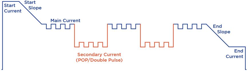
What is Pulse-on-Pulse (Pop / double-pulse) ? This adds an additional pulse 'wave', where the current alternates (or cycles) between the main current level [I2] and a secondary current level [I1]. This effectively multiplies the benefits of single-pulse, with even better thermal control, weld quality/appearance, etc.
Typical Pulse Weld Cycle:
- Start Current: Typically higher than main current, helps to break through the oxide layer when welding aluminium
- Start Slope: For smooth transition from start current to main current
- Main Current: Main welding current
- Secondary Current (PoP / Double-Pulse only): Typically lower than main current, for cooler weld pool
- End Slope: For smooth transition from main current to end current
- End Current: Typically lower than main current, to allow controlled & aesthetic finish to the weld (eg crater filling)
See #12 below for more detailed explanation of pulse functions & settings.
2. Initial Set Up [IMPORTANT!]
When setting up your 220MP for the first time, you will need to make the following changes and checks before using the machine.
Warranty Registration:
To qualify for full / extended warranty, your machine must be registered. Click Here to register.
Software Program Update:
To continually improve user experience, updates can be made to the "Wave OS" operating software at any time. This means that your machine may not necessarily have the most recent software/program version. To ensure that you are using the very latest program, see section #15 in this manual below for instructions on how to check / update the software.
Torch Liner:
The MIG torch supplied with the 220MP is factory-fitted with a steel 0.6-0.8mm 'blue' liner.
If you are welding with Aluminium (or aluminium-bronze) wire, this steel liner should be removed & replaced with the polymer/teflon liner supplied with the machine.
How to fit teflon (aluminium) liners
If you are welding with steel or stainless-steel wire 0.9mm or above, you will need to buy and fit a steel 0.9-1.2mm 'red' liner (Weldclass part no. P3-BRSL3).
Silicon-bronze wires can be used with either poly/teflon or steel liners.
Drive Roller:
The 220MP is factory-fitted with a V-groove roller for 0.8/0.9mm steel. If you are welding Aluminium, this should be removed & replaced with the U-groove 1.0/1.2mm aluminium drive roller supplied with the machine. See #5 below for more information on drive rollers.
Contact Tip:
You will likely need to replace the contact tip in the torch, with the correct size tip to match the wire you are using. An assortment of tips sizes are supplied with the machine. See #8 below for more information on contact tips.
MIG Torch:
The 220MP is supplied with a BZL-25 torch with remote +/- current adjustment controls. See #9 below for more details on torch operation.
Additional torch? If you frequently weld aluminium but also want to occasionally weld with steel or stainless wire, you may want to consider purchasing an additional torch for steel/stainless - and keep the existing torch (with remote controls) as your 'aluminium' torch. This will avoid the inconvenience of having to change liners in the torch. For an additional torch, we recommend the Weldclass Promax BZL 25 torch, either 3m or 4m.
Why is the MIG torch 3m? The remote-control MIG torch supplied with the 220MP is 3m long. This is the optimum length for successful & consistant wire feeding of aluminium, which is critical in pulse applications. If you need a torch longer than 3m, we recommend the Weldclass 8m push-pull torch.
Earth Clamp & Lead:
Ensure that the clamp is very firmly fitted to the earth cable. This is essential for successful pulse welding. See #14 below for more information.
The earth lead should be connected to the negative (-) terminal.
Machine Name:
We recommend adding a name for this machine to the machine software. This will assist with easy identification in the event of using multiple machines, servicing, or exchanging data/settings between machines.
Naming convention is up to you, but one approach is to use a ficticious name plus the year & month (YYMM) of purchase. For example: "BOB2112".

3. Material Thickness & Wire Size [IMPORTANT!]
Material Thickness
When considering material thickness, it is important to understand:
- The material thickness selection in the 220MP program settings (all modes except for Manual) is an approximate guide only. Every application is different and in some cases it may be necessary to dial up either a higher or lower setting vs the actual material thickness being welded
- The 'maximum weldable thickness' will be less in pulse modes than it will in non-pulse modes. This is because pulse is more complex than conventional MIG, with multiple current levels, and requires more power than conventional MIG to weld the same material thickness.
- The same applies to Single-Pulse (AB Pulse mode) and Double-Pulse (PoP mode): Single-pulse will typically allow welding of slightly heavier materials compared to double-pulse.
- Maximum thickness capacity will vary depending on the application. One important factor is 'heat sink'. Larger workpieces / components absorb more heat (especially aluminium which is a very good thermal conductor), which means more/higher current is required, which then reduces the maximum weldable thickness.
- If welding VERY THIN steel or stainless material (for example 0.5mm), welding with non-pulse mode will often give a better result than pulse. This is because the pulse wave cannot operate effectively within the very low/narrow current parameters needed. The ATC (advanced thermal control) technology built into the 220MP is designed for exactly this application. ATC delivers a very 'controllable' arc at low parameters, for superior results when welding very thin material in conventional MIG mode.
220MP Approximate Material Thickness Guide
|
Wires → |
Aluminium |
Stainless-Steel |
Mild Steel |
Bronze |
|
PoP |
0.8*-5mm | 0.8-5mm |
n/a |
0.8-5mm |
| AB Pulse (single pulse) | 0.8*-6mm** | 0.8-5mm | n/a | 0.8-5mm |
|
Manual |
3-8mm | 0.5-8mm |
0.5-10mm |
0.5-5mm |
|
Synergic |
0.8*-5mm | 0.5-5mm |
0.5-5mm |
0.5-5mm |
|
Root MIG |
n/a | n/a |
1.5-10mm |
n/a |
* Welding very thin aluminium (less than 2-3mm) is very challenging, and will require higher levels of experience and skill.
**Weld 6mm using 5mm program
Aluminium Wire [AlMg5, AlSi5, AlMg-Mn]
Being a soft metal, wire feeding with aluminium can be challenging. For successful wire feeding, we strongly recommend using ø1.0mm or ø1.2mm aluminium wire.
Even if you are welding thinner material, there is very rarely any need to chose wire smaller than ø1.0mm. This is especially the case with Pulse MIG, which allows welding of thin materials on larger diameter wires.
Avoid using ø0.9mm wire where possible, and especially avoid ø0.8mm which can be extremely difficult to wire feed. The 220MP does not currently offer a ø0.9mm aluminium wire program, for the above reasons. If there is some reason why you cannot avoid using ø0.9mm wire, we suggest using the ø1.0mm program.
Stainless Steel Wire [Ss]
The 220MP has programs for running 0.8mm, 0.9mm & 1.0mm stainless wires. All these wire sizes will weld down to approx 0.5-0.8mm material thickness, depending on the program. 0.8mm & 0.9mm are the most popular / common wire sizes.
Steel Wire [Fe]
While 3-phase pulse machines are used for welding heavy steel, pulse is not a recommended process for welding of mild steel in the thickness range that is achievable with single-phase power.
For this reason, solid steel wire can only be used in the Non-Pulse (Manual, Synergic and Root MIG) modes. In these modes, the 220MP will offer outstanding results when welding thin material (down to 0.5mm), thanks to ATC (Advanced Thermal Control) technology.
Synergic MIG mode has programs for 0.6mm, 0.8mm, 0.9mm & 1.0mm steel wire.
Root MIG mode has programs for 0.8mm, 0.9mm & 1.0mm steel wire.
Silicon Bronze [CuSi3] & Aluminium Bronze [CuAl8] Wire
The 220MP has programs for running 0.8mm, 0.9mm & 1.0mm bronze wires.
Note that when using CuSi3 (silicon bronze) wire, MIG Synergic (non-pulse) program offers the option of Ar (100% argon) or Ar/Co2 (mixed) gas. However the Pulse programs only have Ar gas option, as 100% argon is required to achieve a good result when pulse welding this wire.
4. Spool Hub Set Up
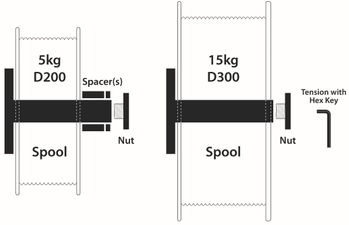
- Install with spool as shown above
- For 200mm / 5kg spools, use spacer(s) as shown above. Use one or both spacers as required, depending on spool width
- Set correct tension on the spool, using hex key. The Spool tension should be enough to brake the spool & prevent free-wheeling. Do NOT over-tighten, as this will put undue strain on the drive system.
5. Drive Roller Selection

It is important to select the right drive roller type to match the wire you are using.
Aluminium wires: Use U-groove roller (a v-groove roller will squash softer Aluminium wire out of shape). The 220MP is supplied with a 1.0/1.2mm U-groove roller.
Solid Steel & Stainless wires: Use V-groove roller. The 220MP is supplied with a 0.8/0.9mm V-groove roller.
Bronze ("brazing") wires: Use with V-groove rollers.
The 220MP is factory-fitted with a V-groove roller. If you are welding aluminium, you will need to remove this & replace it with the the U-groove roller supplied with the machine.
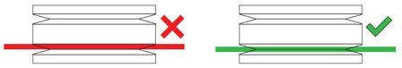
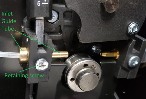
6. Drive Roller Alignment [IMPORTANT!]
Each drive roller will have two grooves for different wire sizes. Make sure that the drive roller is installed so that the groove being used is the correct size for the wire size you are using.
VERY IMPORTANT:
Make certain that the wire is sitting directly & firmly inside the groove in the roller, before closing/locking the tension arm.
Check the Inlet Guide Tube shown below. If this is slightly crooked, it will prevent the wire from being aligned precisely with the drive roller groove. You may find it easier to sight wire alignment by using the camera on your phone.
If guide tube / wire appears to be mis-aligned: Loosen the retaining screw, remove the Inlet Guide Tube, clean the guide tube and its locating hole to remove any dirt/debris, then replace and check alignment again.
7. Wire Feed Tension Arm
Tension should be enough to maintain consistent wire feed with no drive roller slippage, but no more.
Avoid the temptation to wind up / increase the tension as "instant fix" for wire feed issues. Excessive feed tension will not only cause premature wear of the drive roller, bearings and motor/gearbox - but it can also 'squash' the wire out of shape and make the problem worse. If wire is not feeding correctly, check for all other causes (as listed in this guide) first.
8. Contact Tips
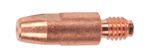
Ensure that the contact tip in the torch is the correct size for the wire you are using.
Aluminium wire requires slightly "over size" tips. These will usually be available as a specific aluminium tip. For example a 1.0mm aluminium tip will be marked as "1.0A" or "1.0ALU".
Sometimes it may also be necessary to use an over-size tip for steel and stainless wire, especially if wire jamming occurs when the torch becomes hot. This is often because the heat causes the wire and the tip to expand (which shrinks the hole in the tip). Using an slightly oversize tip can prevent this. Use an 'aluminium' tip, or go up one tip size (eg: for 0.9mm wire, use a 1.0mm tip).
If the contact tip is worn (or is too large), this will result in wire arcing out inside the tip, causing wire jamming. If this is occuring replace the tip.
9. MIG Torch (Standard)
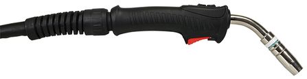
The 220MP is supplied as standard with a BZL 25 series 3m torch with remote +/- amp controls. To activate remote controls, simply connect the remote control plug into the control socket on the machine.
On all MIG modes except for Manual, this will allow you to adjust the Main Current [I2] output from the torch at any time. This will simultaneously change Main Current [I2], Wire Speed & Material Thickness. It will also change the other parameters that are set as a % of main current; start current [IS], end current [IE] and (if you are in PoP double pulse mode) secondary current [I1].
In Manual MIG mode, the torch controls will change the wire speed setting.
If you prefer to de-activate the torch controls, simply disconnect the control plug from the machine.
Torch Consumables: Front-end parts Contact Tips M6x6 Contact Tips M6x8 Teflon/Poly Liners Liners for Steel
Why is the MIG torch 3m? This is the optimum length for successful and consistent wire feeding of Aluminium. (Having very smooth and consistent wire feed is critical in pulse applications). If you need a torch longer than 3m for welding Aluminium, we recommend the Weldclass 8m push-pull torch.
Additional torch? If you frequently weld Aluminium but also want to occasionally weld with steel or stainless wire, you may want to consider purchasing an additional torch for steel/stainless - and keep the existing torch (with remote controls) as your 'aluminium' torch. This will avoid the inconvenience of having to change liners in the torch. For an additional torch, we recommend the Weldclass Promax BZL 25 torch, either 3m or 4m.
10. Push-Pull Torch (Optional)

The optional Platinum PP365 Push-Pull MIG torch has been configured specifically for use with the 220MP and is ready to 'plug & play'. View details of this torch here and contact your Weldclass distributor for pricing & supply.
Consumables & Parts
Front-end parts Contact Tips M6x8 Contact Tips M8x10 Teflon/Poly Liners
Loading Wire
- Lay PP torch out straight
- Ensure that the liner is pushed firmly into the PP torch (you should be able to see the very tip of it under the torch handle hatch). Leave the excess liner protruding from the torch connection.
- Remove brass guide tube from inside of Euro torch connection in machine
- Connect PP torch to the machine, feeding the excess liner through the torch Euro connector & up to the drive rollers
- Cut off liner 2-3mm from drive roller
- Remove Contact Tip on torch
- Disengage drive system rollers/lever in the machine
- Before feeding the wire into the rollers and torch, try to ensure that the first 100mm+ of the wire is as straight and burr-free as possible.
- Load wire into rollers and through the torch liner
- Re-engage drive system rollers/lever in machine
- Press ‘wire inch’ button to feed wire into torch
- Calibrate drive tension in the machine – just enough pressure so that it feeds without slipping under a little bit of load (pinch wire whilst feeding to apply a little pressure)
- Ensure the torch remains as straight as possible until the wire feeds right through the torch*
- Once wire feeds right through the torch replace the contact tip and cut off excess wire
*If the wire gets stuck at the handpiece and causes birds-nesting in the machine you will need to cut wire off inside the machine and go back to step 7. You may have more success manually winding the wire through the torch by rotating the spool (instead of using the ‘wire inch’ button). This way you can carefully feed the wire into the handpiece without birds-nesting. A second person holding and twisting the handpiece, whilst manually feeding, may also help.
Calibrate Wire Feed Speed
The inline drive capsule mounted on the multi-pin push-pull torch lead synchronises the wire speed of the torch motor to the wire feed of the 220MP machine, so that both are 'relative'. The principle that a push-pull torch operates on is that the torch motor/wire feed should be turned slightly faster that the welding machine wire feed to ensure there is positive tension on the wire - but not too fast to avoid the torch drive from 'chewing' up the wire.
The speed of the torch drive motor (relative to the machine) can be tuned using the potentiometer screw on the inline drive capsule (mounted on the torch control lead that plugs into the front of the machine). If you feel the torch motor is spinning too fast on the wire, turn this screw anti-clockwire to reduce speed.
Disengage Rollers
The grey lever inside the PP torch handpiece is used to disengage the feed rollers. If this lever won’t move, you will need to back off the roller tension until it will move. Note that it only moves 1-2mm when disengaged but it should ‘click’ into disengaged position.
11. Expert vs Easy Mode
Easy Mode: Available in AB Pulse (single pulse), MIG Synergic and Root MIG modes. Simplifies the 'welding screen' so that only the two main parameters are shown; material thickness selection and arc-length. Also displays a corresponding weld seam illustration for easy visual reference. Other settings can be easily accessed via the settings button, however they cannot be added to the 'welding screen' display. Recommended for beginners who are becoming familiar with pulse MIG welding; simplifies controls & prevents unintentional adjustment of the wrong parameter.
Expert Mode: This allows the user to add or remove any parameter to display as a 'shortcut' on the welding screen.
To change between these two modes, go to Main Menu (right button) & follow this path;

12. Controls, Modes & Settings [Popular]
Control Panel

MIG Functions & Settings:
MIG Manual
Non-pulse conventional MIG mode, where Voltage & Wire Speed (amps) are set independently.
Synergic
Machines with Synergic controls are pre-programmed with intelligent data that allows the operator to first select the wire type/size, material type and gas type, and the machine will then automatically adjust voltage and amps/wire speed together based on the material thickness selected. Except for 'Manual', all other MIG modes on the 220MP are Synergic, including: MIG Synergic (non-pulse conventional MIG), AB Pulse (single pulse), AB POP (double pulse) and Root-MIG.
MIG Synergic
Non-pulse conventional MIG mode, with synergic controls as explained above.
AB Pulse
Single pulse mode. Automatically switches (or pulses) output between a high peak current and low base (or ‘background’) current. Advantages include; cooler weld, less distortion, better penetration, higher welding speed and cleaner welds with little or no spatter. In some applications, single pulse will allow welding of slightly heavier material compared to double pulse.
AB PoP
Stands for Pulse-on-Pulse, or Double-Pulse mode. Adds an additional pulse wave, where the current alternates (or cycles) between the main current level [I2] and a secondary current level [I1]. In addition to the benefits of single pulse, this allows for aesthetic welds and cooler weld pool, especially useful when welding out-of-position (such as vertical and overhead).
Bi-Level
This is a unique feature which allows the operator to "manually double pulse" by using the torch trigger to switch/alternate between main current [I2] and secondary current [I1]. See below #13 for more information.

Root MIG
A non-pulse program, used with steel wire only. Enables gap-filling & first-pass root welding of pieces that are spaced apart (poor fit-up, gaps, cracks, etc) that traditionally would only be achievable by TIG welding. Weld pool is typically colder than the arc for very low heat & minimal distortion. 
Current
Output in amps. Note that (with exception of manual mode), Current, Wire Speed, Voltage & Material Thickness are all linked and will be simultaneously adjusted when one setting is changed.
Start Current [IS]
Current level (amps) at start of the weld. Set as a % of the main current [I2]. When welding aluminium, typically this will be higher than the main current (>100%), to help break through the oxide layer for a clean start to the weld. Adjustable from 0% to 200% (or maximum machine output).
Start Current Time [ISt]
Duration of start current in seconds. Adjustable from 0s to 10s in 0.1s increments. Note that in some trigger modes, start current time may be disabled &/or overridden by the trigger.
Main Current [I2]
Main welding current / amps. (Yes it can be confusing calling this "I2", we can all thank the faceless boffins who created international electronic codes for this!). This can also be adjusted via the +/- remote controls on the torch.
Secondary Current [I1]
Also known as Background Current. Used in PoP (double pulse) or AB (single) Pulse with Bi-level trigger mode. Set as a % of main current [I2]. Typically this will be lower than the main current (<100%) for a cooler weld pool. Adjustable from 0% to 200% (or maximum machine output).

End Current [IE]
Current level (amps) at the end of the weld. Set as a % of the main current [I2]. Typically this will be lower than the main current (<100%). End Current & End Slope work together to prevent/minimise 'craters' etc for a clean & aesthetic finish to the weld. (Also known as crater fill). Adjustable from 0% to 200% (or maximum machine output).

End Current Time [IEt]
Duration of end current in seconds. Adjustable from 0s to 10s in 0.1s increments. Note that in some trigger modes, end current time may be disabled &/or manually overridden by the trigger.

Start Slope Time [SL.S]
Gradual change in output from start current [IS] to main welding current [I2]. Adjustable from 0s to 10s in 0.1s increments.

End Slope Time [SL.E]
Gradual change in output from main welding current [I2] to end current [IE] . Adjustable from 0s to 10s in 0.1s increments.

Pulse Frequency [Pop Hz]
Used in PoP (double pulse) mode only. Adjusts the pulse 'cycle' (main current pulse, followed by secondary current pulse) frequency in Hz (cycles per second). Ajustable from 0.2-10.0 Hz.

Pulse Balance [t2]
Used in PoP (double pulse) mode only. Adjusts the length (%) of the main current pulse within each cycle. Increasing this % means the main pulse will be longer and the secondary pulse will be shorter. Typically main current will be higher than secondary current, in which case increasing balance % will increase 'heat'. Ajustable from 1-100%.

Arc Length
Also known as arc control or trim. Adjusts the distance from the end of the wire to the weld pool*.
If arc length is too short (longer wire stick out) the arc will be very 'crackly' and produce a lot of spatter. Typically, a longer arc (shorter wire stick out) will result in a more fluid weld pool, flatter weld profile & reduced spatter. If too long this can make the weld black and cause porosity.
There are seperate settings for the Arc Length for; Start Current [S], Main Current [2], Secondary Current [1] and End Current [E]. All are adjustable from a range of -10 to +10.
*In pulse modes, adjusting Arc-Length will also automatically adjust/callibrate some other background settings such as inductance.
Pre-Gas Time
Adjusts 'delay' time from when trigger is pulled and arc/wire-feed starts, to ensure effective gas coverage and prevent porosity etc at the start of the weld.

Post-Gas Time
Adjust time that gas continues to flow after welding stops, to ensure effective gas coverage and prevent porosity etc at the end of the weld.

Inductance
Available in Manual, Synergic & Root MIG modes only*. In some respects, inductance is like adjusting the nozzle on a garden hose. Low inductance = wide, smooth, fluid arc, can reduce spatter and improve weld appearance. High inductance = narrow, focused, crisp arc which can increase spatter levels, but in some applications (especially thinner materials) allows a tighter 'pin point' weld bead. Adjustable from -50% to +50%.
*In Pulse modes, inductance is automatically adjusted based on arc length & other settings.

Burn-Back
Burnback adjustment controls brief time that the wire feed will continue after the trigger is released and welding current stops. If wire feed and current stop at exactly the same time, the wire will still be hot and will ‘burn back' and stick to the tip. If this is occuring, increase burnback. If the burnback is too high, this will leave excessive wire ‘stick out’ that will need to be corrected before starting the next weld. Adjustable from 0-1.0sec, in 0.01s increments.

Soft-Start / Hot-Start
Available in Manual MIG mode only*. When a weld is started, the workpiece and the wire will be cold compared to welding temperature, and if full wire speed is applied immediately this can cause an uneven and poor start to the weld. To prevent this, Soft-Start gradually accelerates wire speed at the start of the weld. If you find the wire ‘bumping’ the workpiece before the arc is fully established, try increasing Soft-Start setting. Ajustable from 1-100%.
*In all other modes this is replaced by Start Current and Slope settings

Spot Time [t SPOT]
Used in Spot trigger mode. Adjusts duration of spot welding arc time. Adjustable from 0-1.0sec, in 0.01s increments.

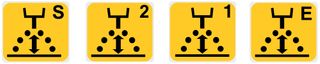
13. Trigger Modes
2T
Pull & hold trigger to start & continue welding
Release to initiate end slope/current

4T
> Pull & hold trigger during start current/slope
> Release when main current begins*
> Pull & hold to start end slope/current
> Release when welding stops**
*Or release during start current/slope to skip immediately to main current.
**Or release during end slope/current to immediately stop welding.
4T Bi-Level
Use in AB Pulse (single pulse) mode only. This is a unique feature that allows the operator to "manually double-pulse".
> Pull & hold trigger during start-current & start-slope
> Release when main current begins*
> Pull & release quickly to switch/alternate between main current & secondary current
> Pull & hold to start end slope/current
> Release when welding stops**
*Or release during start current/slope to skip immediately to main current.
**Or release during end slope/current to immediately stop welding.
14. Dos & Don'ts [IMPORTANT!]
Clean materials thoroughly before welding:
Always clean the base material thoroughly before welding. Any oxide on the aluminum surface should be removed with a stainless-steel wire brush
Push Technique:
Use push (rather than drag) torch technique
Earth and Cables:
For successful pulse welding, it is absolutely critical that there is no disruption or "leakage" anywhere along the current path. This is the #1 cause of malfunctions with pulse MIG welding, and is the first thing you should check if you are experiencing problems.
- Earth clamp must be in good condition and firmly fixed to the cable with no loose parts.
- If your earth clamp needs to be replaced, our #1 recommendation is the Platinum EC500H Heavy-Duty Earth Clamp
- Cables must be in good condition: No worn insulation or exposed copper wire
- Torch must be in good condition
- Check that that all connections (for torch & cables) are tight/firm
- Where possible attach the earth clamp directly onto the job / workpiece, as close to the weld zone as possible.
- Avoid excessively long earth cables (ideally not more than 4m)
- Keep torch and earth cables as straight as possible and avoid excessive coiling
15. Updating Software Programs
Updates and improvements are constantly being made to the "Wave OS" operating software, to provide the best user experience across the many programs/settings available.
Before using your machine for the first time, we highly recommend you update your machine to the latest program version.
Check if your machine has the latest program version:

The screen will display 3 lines of code as below.
Do the numbers shown below in blue match your machine?
Yes: you already have the latest version
No: you have an older version, please update as per instructions below
CODE: XXXXXXXX CRC: 296E
CODE: XXXXXXXX CRC: C6E7
CODE: XXXXXXXX CRC: 9277
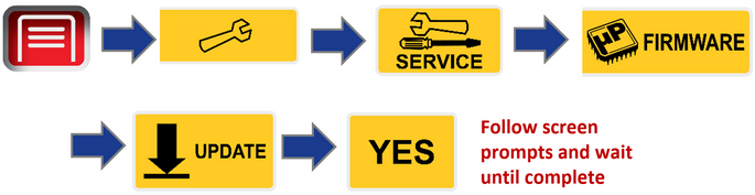
How to update to latest program version:
- Turn the machine on and insert a 'clean' USB stick into the USB port. The USB must not contain any files.
- Following USB icon should appear in bottom left of the control screen. If this does not appear after a few seconds, remove USB, turn machine off & on again, and plug in again.
If icon still does not appear you may - try a different USB, or reformat your USB to "FAT32" format. - Remove USB and plug into a computer. It should now contain a folder named "WDM" (with additional folders inside). If USB does not contain this folder, insert into machine again, make sure machine is turned on and leave in machine for 60 seconds before removing.
- Click button below to download a Zip folder containing the latest program files.
Download Latest Program Update - Released 16/Dec/2021 - Open "Firmware" folder in Zip file & copy the contents (.hex & .tpk files) across to the "FIRMWARE" file on USB
IMPORTANT: Only the .hex & .tpk files within the Zip folder should be copied to the USB, do NOT copy the entire Zip folder itself. - Close USB file, remove USB from computer and plug back into machine
- Follow these steps to update Firmware
- Wait until update has completed, then remove the USB. Congratulations, your machine is now updated with the latest program version!

NOTE: If the update process does not work or stalls at a particular stage, delete all files off the USB, reformat your USB to "FAT32" format and repeat the process. Follow step e carefully to ensure the the correct files are copied from/to the correct folders.
16. Jobs Menu
Information coming soon. Please contact Weldclass if you have any questions.
17. MMA (Stick)
In MMA (stick welding) mode, the 220MP is suitable for running most types of common electrodes up to 4.0mm.
A stick welding lead (Weldclass part number WC-06233) will be required to set up the 220MP for stick welding.
MMA adjustments:
Main current [I2]: Adjustable from 20 to 160 Amps. The corresponding 'suggested' electrode size (from 1.6mm to 4.0mm) will be shown on the display, depending on the current level set.
Hot Start: Provides extra power/current when the weld starts to overcome the high resistance between the electrode and workpiece as the arc is started. It makes igniting the electrode easier and prevents it from sticking when cold. Adjustable from 0 – 100%, as a percentage of main welding current (up to max 160A).
Arc Force: Boosts the welding power if the machine senses the welding voltage is getting too low, to assists with maintaining & stabilising the arc. The higher the arc force adjustment, the higher the minimum voltage that the power source will allow. 0% is Arc Force off, 100% is maximum Arc Force. Useful for electrode types that have a higher operating voltage requirement or joint types that require a short arc length such as out of position welds.
VRD: This is an additional safety feature which reduces the open circuit voltage from 96V down to approximately 15V. When the operator strikes an arc, the VRD will de-activate to supply full voltage and then reactivate when welding stops. VRD can be switched on or off. In some applications, VRD can make it more difficult to start an arc. VRD may be mandatory on some work sites. Note that VRD applies to MMA/stick welding only.
Weldclass Stick Welding Electrodes
18. TIG
In TIG mode, the 220MP is suitable for basic "Lift-Arc" DC TIG welding (20-160A) of mild-steel, stainless-steel, copper and chrome-molly up to a thickness of approximately 3-4mm.
A TIG welding torch is required to set up the 220MP for TIG welding. Compatible Weldclass TIG torch models are 17FV series or 26FV Series.
Note that the 220MP is NOT suitable for TIG welding of aluminium, as this requires machines with AC/DC TIG function - such as the Weldclass 202T AC/DC TIG welder.
19. Errors & Troubleshooting
|
Error or Fault |
Suggested Cause / Remedy |
|
Display showing ALARM OUTPUT SHORT CIRCUIT |
|
|
Settings not saved / retained when machine turned off & on again. |
|
|
xxx |
xxx |
FAQs
Why doesn't the 220MP have pulse mode for Mild Steel wires ?
The 220MP can be used to weld mild-steel wires in non-pulse (Manual, Synergic or Root MIG) modes, however not in pulse modes. There are several reasons for this;
Firstly, mild-steel does not present the same "thermal challenges" as other metals (such as aluminium or stainless), and therefore pulse does not necessarily offer the same advantages. In many mild-steel applications, pulse welding is not the best process. Pulse MIG can offer some advantages for welding heavy steel, however this requires a higher "peak" current which is beyond the output range of single-phase welding machines and is possible only with three-phase pulse machines.
If welding thin mild steel material, the 220MP will offer exceptional results in the non-pulse programs, due to the ATC (Advance Thermal Control) feature and especially so in Root MIG program which allows "gap-filling" (including on thin material) that would normally only be achievable with TIG.
Why doesn't the 220MP have reverse-polarity / gasless wire capability ?
With pulse welding, it is absolutely essential that there are no loose connections anywhere along the "current path" - including machine internals, torch and earth lead. As the 220MP has been designed primarily for pulse welding, the option of reverse polarity - for welding with gasless wire - has been deliberately excluded on this machine; a) because pulse is not applicable for gasless wire, and b) this minimises the number of connections, to prevent issues that may be caused due to incorrect polarity, or worn/faulty/infirm connections.
Why is the MIG torch supplied with the 220MP 3m long? Can the 220MP be used with a 4m torch?
The remote-control MIG torch supplied with the 220MP is 3m long. This is the optimum length for successful and consistent wire feeding of Aluminium, which is especially critical in pulse applications. If you need a torch longer than 3m, we recommend the Weldclass Platinum PP365 8m Push-Pull torch.
If welding with steel or stainless-steel wires, a standard 4m torch can be used if required. For this we recommend the Promax BZL 25 torch.
Why is the drive system 2-roll and not 4-roll ?
Reliable and consistent wire feeding is certainly essential for successful pulse MIG welding. To achieve this, traditional machines with "100% mechanical" drive controls rely on 4-roll drive systems. The 220MP however, uses a Swiss-made intelligent wire drive system with electronic Tacheometric Control. This means that the machine software monitors wire feed speed against weld parameters, at intervals of more than 100 times per second, and self-calibrates the wire feed speed, for exceptionally smooth and consistent wire feeding.
The result is wire feed that is not only as reliable as any 4-roll system, but is also live-synchronised with feedback from the arc parameters, to automatically compensate for any changes in the arc conditions. This helps make the 220MP simple and user-friendly to operate, so the operator can "set and forget" rather than spend time continually having to tweak machine settings.
Also, being a portable single-phase machine, weight is obviously an important factor and utlilising an intelligent 2-roll system (rather than a heavier 4-roll system) contributes to the 220MP being one the most compact and lightweight machines in its class (22kg).
Why do the Pulse programs only allow welding up to 5mm thickness?
In Non-Pulse manual mode, the 220MP will weld up to 10mm mild steel or 8mm aluminium.
However in Pulse modes, the maximum material thickness setting is 5mm (aluminium, stainless, bronze). This is becuase pulse welding is more complex, with a lot more parameters to consider for than standard non-pulse MIG welding. A typical pulse current wave requires multiple current levels (start, base, peak, secondary & end current), which all have to be factored into the maximum output power that is available from single phase. For this reason, successful Pulse MIG welding of materials up to and above 10mm requires 3-phase machines.
Pulse welding of up to 5-6mm material may be achievable in most cases using the 220MP 5mm pulse programs, however to weld material thicker than this we recommend using non-pulse Manual mode. See section #3 above for more detail.
.