
Shop Now
From Our Blog
-
FURY MPST Series: How-To Videos
Video guides for Weldclass FURY MPST Series MIG/TIG/Stick Pulse welding machines. -
What is a Pulse MIG? A how & why guide to Pulse MIG welding
The how, what and why guide to pulse MIG welding


MIG Welder Wire Feed Troubleshooting Guide
MIG welder wire feed not working? Wire jamming? Here's a checklist to help you identify the cause and optimise the performance of your MIG welder. These tips apply to virtually any make and model MIG welder.
Do's and dont's for successful wire feeding & great welds!

More tips for specific Weldclass MIG machines
Check the basics first
We've all done it; cursed our machine and wasted time, only to find we've overlooked something basic.
Check these things first and you could save yourself a lot of time and hassle.
Earth lead & Clamp: Yep, one end connected to the welder & the other to the job!
Polarity: Check and double check you have the correct polarity for the wire you are using. Most "solid" wires should be used with Torch/Wire + and Earth -. Gasless wires should be used with Torch/Wire - & Earth +.
Connections: This is far more important than what many welders realise. Just like a leaky garden hose, a loose connection anywhere along the current path will compromise the performance of your welder. Check that all connections are tight/firm and in good condition, including: MIG torch and earth lead connection to the welder, any polarity connections (sometimes inside the wire feeder compartment), earth lead cables, any cable joints & lugs, earth clamp, etc. Worn or damaged cables, connections and earth clamps should be replaced. More on this topic here.
Spool Hub Brake Tension
Spool tension should be enough to brake the spool & prevent free-wheeling. Do NOT over-tighten, as this will put undue strain on the drive system.
Drive Roller(s) Selection
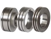
It is important to select the right drive roller type to match the wire you are using. Here's a rule-of-thumb;
Solid Steel & Stainless wires: V-groove roller
Gasless & Flux-Cored wires: Knurled roller where possible (to grip the softer flux-cored wire). V-groove will often work OK as an alternative.
Aluminium wires: U-groove roller (a v-groove roller will squash softer Aluminium wire out of shape)
Bronze ("brazing") wires: U-groove where possible, otherwise V-groove
Drive rollers for Weldclass MIG welders
Drive Roller Alignment
Most drive rollers will have two grooves for different wire sizes. Make sure that the drive roller is installed so that the groove being used is the correct size for the wire size you are using.
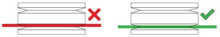
VERY IMPORTANT: Make certain that the wire is sitting directly & firmly inside the groove in the roller, before closing/locking the tension arm.
Wire Feed Tension Arm
Tension should be enough to maintain a consistent wire feed with no drive roller slippage, but no more.
Avoid the temptation to wind up / increase the tension as "instant fix" for wire feed issues. Excessive feed tension will not only cause premature wear of the drive roller, bearings and motor/gearbox - but it can also 'squash' the wire out of shape and make the problem worse. If wire is not feeding correctly, check for all other causes (as listed in this guide) first.
Contact Tips
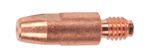
Ensure that the contact tip in the torch is the correct size for the wire you are using.
If wire jamming occurs when the torch becomes hot, this is often because the heat causes the wire and the tip to expand (which shrinks the hole in the tip). This often occurs with gasless wire, where the torch will typically run hotter without the cooling effect of gas. Using a slightly oversize tip can prevent this – eg: for 0.9mm wire, use a 1.0mm tip.
Aluminium wire also requires slightly "over size" tips. These will usually be available as a specific aluminium tip. For example a 1.0mm aluminium tip will be marked as "1.0A" or "1.0ALU". These tips can also be used for gasless & flux-cored wire.
If the contact tip is worn (or is too large), this will result in wire arcing out inside the tip, causing wire jamming. If this is occuring replace the tip.
Torch Liner
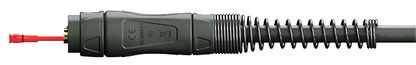
Ensure that the liner (fitted inside the torch cable) is the correct type and size for the wire you are using.
Steel wires require a steel liner, Aluminium wires require a teflon or polymer liner.
Liners are typically available in size ranges, for example 0.6-0.8mm, 0.9-1.2mm and so on. If the liner is too small this will cause wire jamming, if too large it will allow the wire to 'snake' and jam.
Liners are a consumable part and should be replaced periodically as they gradually fill up with particles and wear internally. There's no hard & fast rule, but if your MIG torch has done a lot of work and you're having wire feed problems it may be time to replace the liner. Do NOT blow out the liner with compressed air! It may be tempting to do this as quick fix, but A) This can damage the gas tube around the liner, and B) this won't improve the liner if it is worn & needs replacement.
MIG Torch & Parts ID Guide How to fit steel liners How to fit teflon (aluminium) liners
Drive Motor/Roller Rotates But Wire Is Jamming / Inconsistant
If the wire drive motor/roller is working normally and rotates when you pull the trigger on the torch, you should then test the wire feed through the torch cable.
Firstly, remove the MIG torch from the machine (unless your machine has a direct-connect / hard-wired torch).
With torch removed from the machine, feed a length of wire (at least 2-3m longer than the torch) through the torch & then pull it through manually from the handpiece / contact tip end. Slight resistance / friction is normal , however if it requires strong force to pull the wire, this suggest that the problem is in the torch. Follow the suggestions above relating to the torch parts, including the contact tip & liner.
Drive Motor/Roller Does Not Rotate
If the wire drive motor/roller do NOT rotate when you pull the torch trigger, this could indicate a problem with either a) the torch trigger/circuit, or b) the machine or drive system.
To determine if the problem is in the torch, test the wire drive system in the machine with the torch removed:
- First disconnect the earth lead for safety precaution.
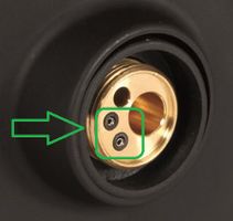
- Take a short legth of wire bent into a U-shape, and place this against both of the trigger socket terminals in the Euro torch connection on the front of the machine - see below. (Note these trigger terminals do not carry electrical current).
- This will simulate the torch trigger function to active the drive system
If drive system works (motor/roller rotates), this indicates a problem with the torch trigger/circuit. Check and/or replace the torch trigger. The trigger wires that run along/inside the torch cable could be damaged, you can partially inspect these by removing the casing at handle and connection end. Alternatively, replace the complete torch.
If the drive system does not active (motor/roller does NOT rotate), this indicates a problem with either the drive motor/system itself, or an electrical fault inside the machine. You may need to take your machine to a qualified repairer.
Wire feed set up for specific Weldclass MIG welder models