
Shop Now
From Our Blog
-
FURY MPST Series: How-To Videos
Video guides for Weldclass FURY MPST Series MIG/TIG/Stick Pulse welding machines. -
What is a Pulse MIG? A how & why guide to Pulse MIG welding
The how, what and why guide to pulse MIG welding


User Guide - Promax 600 Series Helmets
User guide for Weldclass PROMAX 600 & 850 Series helmets, including: PROMAX 600, PROMAX 650 & PROMAX 680, PROMAX 680R, PROMAX 850R welding helmets.


1. Before you start
Read the instruction manual:
This web guide is an additional resource and does not replace the instruction manual issued with the helmet. The instruction manual should be read before using your helmet.
Warranty Registration:
To qualify for full/extended warranty, please register here within 30 days of purchase.
2. Controls & Settings - Promax 600 and 650
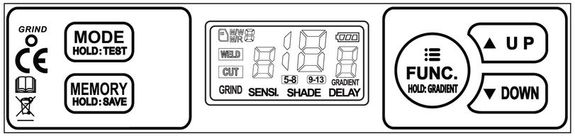
MODE
Press MODE once to change between following modes. Then press UP or DOWN to adjust the shade level within each mode.
Following applies to lenses with serial no. "2022..."
- WELD 9-13: Use for most MIG, Stick or TIG welding tasks
- WELD 4-8: Use for low-amperage welding, plasma cutting, etc
- CUT: Locks the lens to the selected shade level (4-8). Useful for oxy cutting, brazing etc where the light source may not be sufficient to trigger normal auto-darkening function.
- GRIND: Locks the lens to light (shade 3) mode, to allow grinding. 'Grind' LED (top left of controls) will flash when grind mode is activated. On Promax 650 model only, press external button for 3 sec to activate or deactivate grind mode.
Following applies to lenses with serial no. "2023..."
- WELD 9-13: Use for most MIG, Stick or TIG welding tasks. SHADE LOCK function can also be used in this mode, see below ↓
- CUT 4-8: Use for plasma cutting, very low-amperage welding, oxy, etc. Shade lock function can also be used in this mode, see below.
- GRIND: Locks the lens to light (shade 3) mode, to allow grinding. 'Grind' LED (top left of controls) will flash when grind mode is activated. On Promax 650 model only, press external button for 3 sec to activate or deactivate grind mode.
Hold MODE to run a test. The lens will then run through a sequence of settings.
FUNC
When in WELD mode, press FUNC to scroll though following functions. Then press UP or DOWN to adjust these settings.
- SENSI (Sensitivity): Adjust between 0 (lens will not activate at all, this is equivelant to grind mode) and 9 (most sensitive). Adjusts the sensitivity of the arc sensors to best suit the welding task & surrounding environment. Low sensitivity helps prevent the lens from reacting to other nearby light sources. High sensitivity may be required if welding on low current &/or when TIG welding.
- SHADE: Adjust shade to appropriate level for welding task at hand
- DELAY: Adjusts switching time from dark back to light mode, when welding stops.
GRADIENT: Hold FUNC for 2 sec to active or deactive. 'GRADIENT' will appear in top right of LCD screen when activated. When welding welding stops, gradient function will gradually return (slope down) from dark to light, instead of changing abruptly from the welding shade back to light (shade 3). This mirrors the cooling of the weld pool, to reduce eye strain.
SHADE LOCK
This is a recently added feature on lenses with serial no. of "2023...".
In any mode, quick-press UP/DOWN buttons together to 'lock' to the currently selected shade level (lens remains dark and will not switch to light). When shade is locked, the shade level can also be adjusted using UP/DOWN.
Quick-Press UP/DOWN buttons together to unlock and return to the previous auto-darkening settings.
This is useful for any process or application where the light source (eg oxy cutting, brazing ) or the environment / conditions (eg nearby conflicting light sources, awkward welding positions, etc) may interfere with normal auto-darkening function.
MEMORY
Save up to 10 favourite settings.
Lens must be in WELD mode to use/access memory settings. (Lenses with serial no. "2023..." will also allow memory use in CUT mode).
To write a memory setting, first set all welding settings that you wish to save (shade, sensitivty, delay, etc). Then hold MEMORY for 2 sec. 'M/W' will appear in top left of LCD screen, followed by the memory slot number. Press UP or DOWN to select slot that you wish to save to, then wait 5 seconds. 'M/W' will dissapear when the setting has been saved.
To recall a saved setting press MEMORY once. 'M/R' will appear in top left of LCD screen, followed by the memory 'slot' number. Then press UP or DOWN to scroll through slots 0-9.
3. Controls & Settings - Promax 680, 680R, 850R
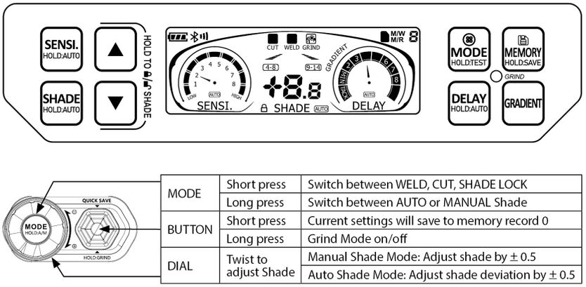
The following instructions apply to internal controls. For external controls (680/680R models only) see diagram/table above.
MODE
Press MODE once to change between following modes. Then press UP or DOWN to adjust the shade level within each mode.
- WELD 9-13: Use for most MIG, Stick or TIG welding tasks. SHADE LOCK function can also be used in this mode, see below ↓
- CUT 4-8: Use for plasma cutting, very low-amperage welding, oxy, etc. Shade lock function can also be used in this mode, see below ↓
- GRIND: Locks the lens to light (shade 3) mode, to allow grinding. 'Grind' LED (top left of controls) will flash when grind mode is activated.
- SHADE LOCK: See description of this mode below ↓
Hold MODE to run a test. The lens will then run through a sequence of settings.
SHADE:
Manual: Press SHADE, then Up/Down buttons to adjust shade level.
Auto: Press and Hold SHADE to activate or deactivate. When in Auto, the helmet will adjust shade level automatically depending on shade intensity. Adjust shade deviation (fine adjustment) in 0.1 increments (up to +2.0/-2.0) using Up/Down buttons.
SENSI. (Sensitivity)
This adjusts the sensitivity of the arc sensors to best suit the welding task & surrounding environment. Low sensitivity helps prevent the lens from reacting to other nearby light sources. High sensitivity may be required if welding on low current &/or when TIG welding.
Manual: Press SENSI, then Up/Down buttons to adjust.
Auto: Press and Hold SENSI. to activate (Auto will display against sensitivity display) or deactivate.
DELAY & TACK MODE
This adjusts switching time from dark back to light mode, when welding stops.
Manual: Press DELAY, then Up/Down buttons to adjust.
Tack Mode: This is the lowest delay setting. In tack mode, the lens will return to shade 5 (instead of shade 3) in between welds, to further reduce eye strain. Ideal when doing repetitive tack welds.
Auto: Press and Hold DELAY to activate (Auto will display against sensitivity display) or deactivate.
GRADIENT
Press GRADIENT to activate ('GRADIENT' will appear on screen) or deactivate. When welding welding stops, gradient function will gradually return (slope down) from dark to light, instead of changing directly from the dark welding shade back to light (shade 3). This mirrors the cooling of the weld pool, to further reduce eye strain.
SHADE LOCK
In any mode, quick-press UP/DOWN buttons together to 'lock' to the currently selected shade level (lens remains dark and will not switch to light). When shade is locked, the shade level can also be adjusted using UP/DOWN.
Quick-Press UP/DOWN buttons together to unlock and return to the previous auto-darkening settings.
This is useful for any process or application where the light source (eg oxy cutting, brazing ) or the environment / conditions (eg nearby conflicting light sources, awkward welding positions, etc) may interfere with normal auto-darkening function.
MEMORY
Save up to 9 favourite settings.
Lens must be in WELD mode to use/access memory settings.
To write a memory setting, first set all welding settings that you wish to save (shade, sensitivty, delay, etc). Then hold MEMORY for 2 sec. 'M/W' will appear in top left of LCD screen, followed by the memory slot number. Press UP or DOWN to select slot that you wish to save to, then wait 5 seconds. 'M/W' will dissapear when the setting has been saved.
To recall a saved setting press MEMORY once. 'M/R' will appear in top left of LCD screen, followed by the memory 'slot' number. Then press UP or DOWN to scroll through slots 0-9.
4. Headgear Adjustments
Proximity Adjustment
To change proximity / distance of the helmet from users face, use quick-release sliding adjustments as shown below.

Size Adjustments
Adjust size of headband (via rear knob) and upper straps as shown below.
Tip: If the upper straps are too tight / short, this will position the headband higher up and prevent it from 'gripping'. Increase strap lengths to allow the headgear to sit lower on the head, so the headband and sweatband can gain a good purchase / grip.
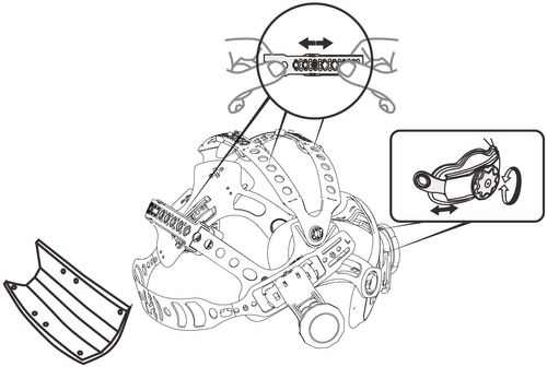
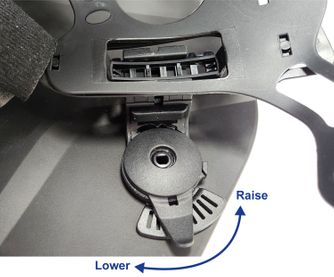
Tilt Stop Adjustment
Adjust tilt stop angle of helmet as show below. This adjusts the 'height' of the helmet when helmet is in the 'flipped down' position. Loosening the adjacent external knob will make this easier.
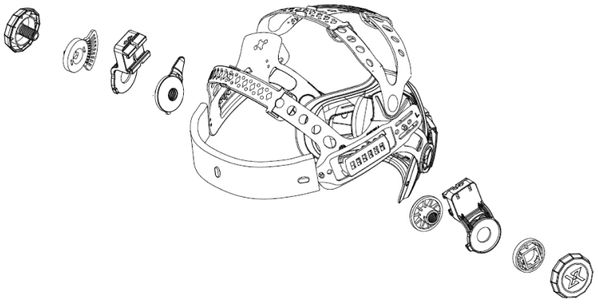
Headgear Assembly Diagram
5. Replacing Cover Lenses
Outer Cover Lens
To remove lens, pull one side of lens forward to 'unlatch'.
IMPORTANT: When fitting a new cover lens, ensure that lens is very firmly 'latched' at all 4 corners. Failure to do this may result in spatter damage/marking to the electronic cassette which will void warranty.
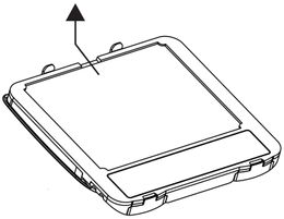
Inner Cover Lens
Using the access point at the top of the cassette (you may need to use small flat-bladed screwdriver or similiar tool), pull the lens back until it bends and the corners of the lens are released.
To fit new lens, bend and push corners of lens into place, starting with top corners.
If magnification lens holder brackets are fitted, it will be easier to temporarily remove these before replacing the cover lens.
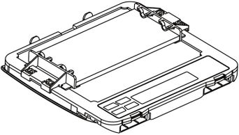
6. Installing Magnification Lenses
Each helmet is supplied with 2 mag lens holder brackets. Clip these into the inside of hemet as shown in video below.
Standard 108x51mm magnification lenses can now be fitted to these brackets.
Brackets are easily removed / unclipped if required, when replacing inner clear cover lens.
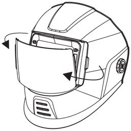
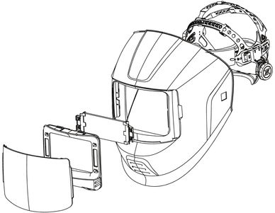
7. Removing Auto-Darkening Cassette
See video below. Note video depicts Promax 650 model with external grind button.
- Promax 650 & 680/680R models only: Remove external grind button by unscrewing button surround. Take care not to pinch or damage control cable during following steps.
- Remove front cover lens
- Note 2 locking tabs inside helmet, above top of cassette/window
- Place one hand inside helmet and with two fingers push each tab downwards firmly
- Cassette will un-latch at top, push/lever cassette forward to remove and slide out of shell
- Reverse above process to replace
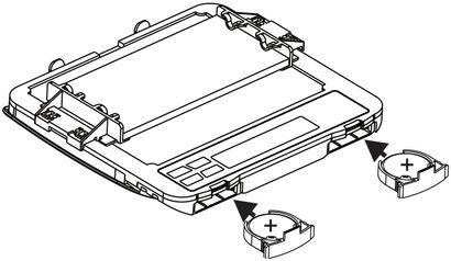
8. Replacing Lens Batteries
2 x CR2450 coin-style batteries are located at the bottom of the cassette. Battery holders are visible from inside the helmet, however these are held in place by safety screws* which can only be accessed by removing the cassette from the shell.
See video below.
- Remove cassette as per steps under #7 above
- Remove battery safety screws* using phillips-head screwdriver
- Remove battery holders
- Replace batteries
- Reverse above process to replace
*Safety screws are required for compliance with Australian Button/Coin battery laws, intended to prevent children from swallowing batteries.
9. Spare Parts
Clink on links below to view more details on each replacement part:
Helmet Parts:
Cover Lens Kit 2 Outer + 1 Inner - PROMAX 600/650/680 (WC-05351)
Cover Lens Inner Pk5 - PROMAX 600/650 (WC-05350)
Cover Lens Inner Pk5 - PROMAX 680/680R/850R (WC-05357)
Cover Lens Outer Pk5 - PROMAX 600/650/680 (WC-05348)
Grinding Visor Lens Pk5 - PROMAX 850R (WC-06709)
Batteries (CR2450) - Not sold by Weldclass, commonly available from any battery supplier
Helmet Shell Parts (including face seals for PAPR helmets)
PAPR Respirator Parts:
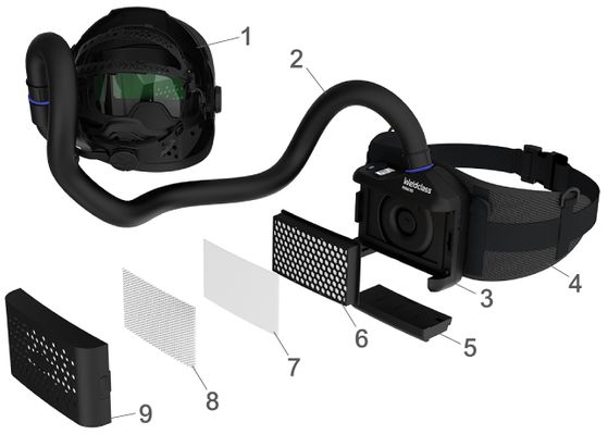
Spare Parts for PROMAX R50 PAPR Respirator (used with PROMAX 680R & 850R Helmets)
11. Maintenance and Troubleshooting